Part No. CPM1500-J-TR-DC-V1 - Case 6-120692-78189 - I/O Replacement Procedure
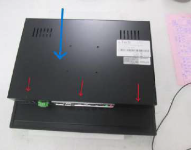
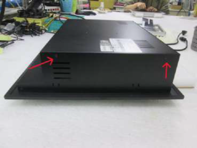
Step 1: Loosed rear cover’s screws ( red marked ) and removed rear cover ( blue marked )


Step 2:
Removed tape and OSD cable ( yellow marked ) / Please see “ Note 1 ”
Removed tape and OSD cable ( yellow marked ) / Please see “ Note 1 ”
Removed power cables ( green marked ) / Please see “ Note 2 ”
Step 3: Loosed I/O screws ( white marked / blue marked ) and new I/O replaced.
Note 1 :
OSD cable connection
Left side ( brown / green marked ) ; Right side ( blue / yellow marked )
Note 2 : Power cable connection ( blue marked ). Please pay more attention.
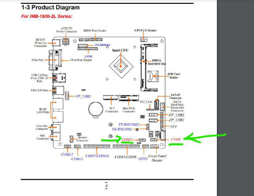
COM 1 & COM 2 Installation
Step 1:
a. COM1 / COM 2 position ( green marked ) and connection.
b. We will provide hard copy and user manual to you.
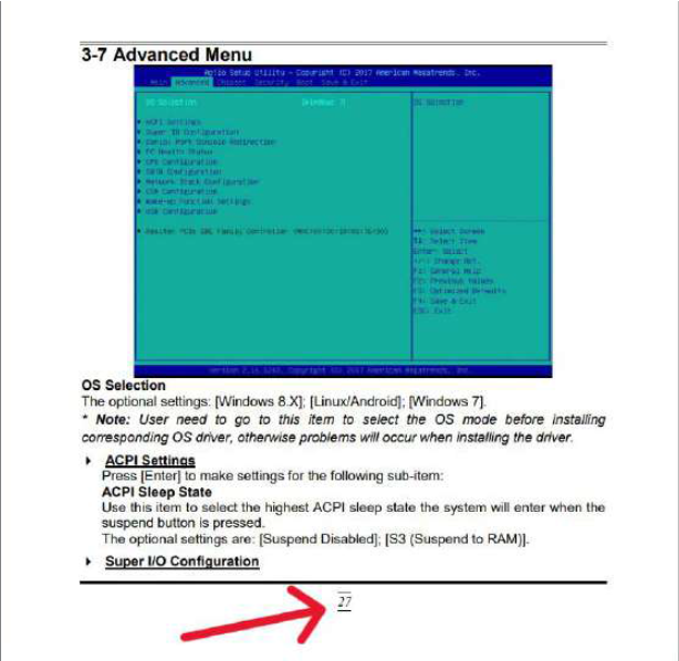
c. We set COM 1 and COM 2 to RS232 mode by jump setting generally and we will go to BIOS / Advanced Mode ( Step 2 ) to double check the setting mode.

Step 2 :
Software ( BIOS ) check
We will provide user manual to you.

Related Articles
Part No. EPMW2155D-FHD-TR-AP01 - Case 6-OW-107744-79412 - DC - DC Power Board Replacement
1. The power board inside of monitor to be replaced. 2. Remove clamp mount brackets on four sides. 3. Remove screws on both of left and right sides of back housing, to separate front bezel/touch/LCD panel sub module from back housing. Remove panel ...How to Remove and Replace Panel - Model: CPMW1560-J-DC-AE1
Part no.: CPMW1560-J-DC-AE1 SO: 110668 Panel Replacement Procedure Step 1. Removed the rear cover (Blue portion) Step 2. Removed Touch cable. (Green portion) Removed Invertor cable ( 1 ) and LVDS ( 2 ). (Red Portion) 3. Loosed the left side, top ...Part No.: YCH1500HB-TR-DC - Case 6-OW-107338 - Male Connector for DC 9-36V Power Input (Model: DC-ME860-508-02G / DC-MC421-350-02G).
Customer Issue: I have a truck of mine that runs a camera system with LCD display provided by your store. The plug was broken or lost or something, anyway, it's just wires showing. Is there a harness you can direct me to, to replace this? Solution: ...Part No.: CPMW2700IP-PCAP-DC - Case 6-120627-78017 - Question: OSD Auto Adjust Function Procedure.
OSD Auto Adjust function Procedure. 1. OSD key function Manual / Select button ---red marked + / Increase or - / Decrease button ----yellow marked 2. Pressed Manual / Select button 3. Pressed + / Increase ) or - / Decrease ) button to “ Special “ ...Part no.: YOP1700HB2WT-TR - Case 6-110118 - How to remove and replace 5 Wires Resistive Touch?
Case 6-110118 Wide Temp -30C to 85C Open frame, 17" LCD monitor, 1280 x 1024, super high brightness 1500 nits VGA Input (Auto dimming control)(without RS232 control) + 17"- 5 Wires Resistive Touch with USB Controller Tools 17" Opem Frame Touch LCD ...