IR Touch Module Assemble User Manual
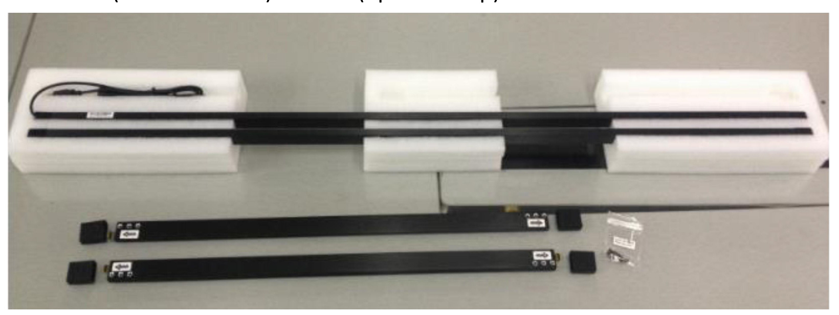
1. X axis transmitting tube : 1 PCS
2. Y axis transmitting tube : 1 PCS
3. Y axis receiving tube : 1 PCS
4. X axis receiving tube : 1 PCS
5. Screws (KM2.5 * 4mm) : 14 Pcs (2pcs backup)
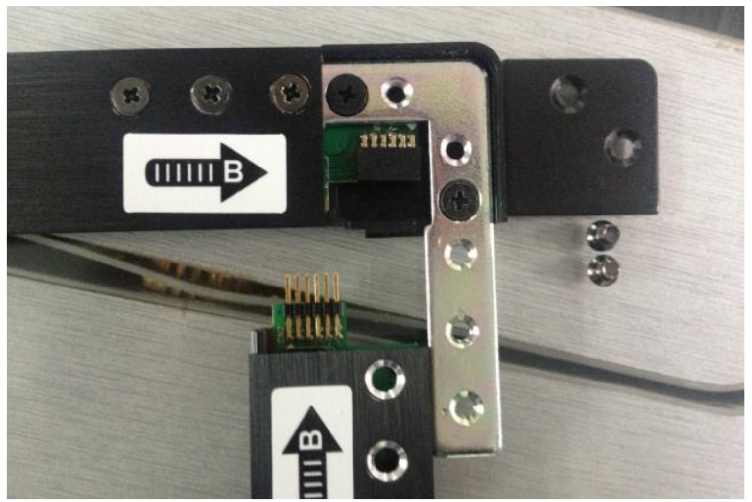
Step 1: Match the No. on the touch frame (No. A match No. A, No. B match No. B, No. C match No. C, No. D match No. D).
Step 2: Open the cover of each corner (as below).
Step 3: Connect the spare part via the 10pin connector and fix the cover of corner.
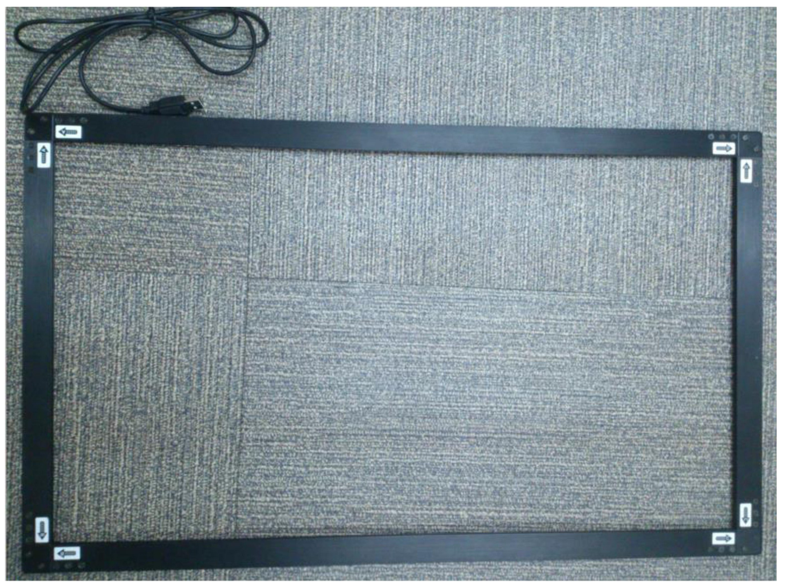
Step 4: According to the same principle, repeat the corner B,C,D and finish the assembling as below.
Attention:
1. Must open the cover of the corner before connecting the frame (as below), in case the 10 pin connector broke.
Related Articles
CAT5 Module User Manual
Click the link below CAT5 Module User ManualIP Module User Manual
Click the link below IP Module User ManualDOT User Manual
Click the link below DOT User ManualDOD User Manual
Click the link below DOD User ManualCCHW5500-SIP User Manual
User Manual Model: CCHW5500-SIP Download here